Description
Description
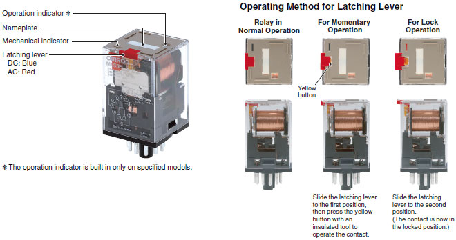
Omron MKS2PIN 240VAC relay. 8 PIN round. Varistor model with lockable test button, plug-in type, Built-in indicator.
Features
- Same mounting and internal wiring as the previous Super MK Relays
- Built-in mechanical indicator enables checking contact operation.
- All materials are RoHS compliant.
- UL and IEC (TÜV) certification
Specs
| Product classification | Monostable relays Built-in LED indicator and varistor type (AC coil) |
| Coil ratings | 240 VAC 9.6 mA (60 Hz) |
| Coil resistance | 4480 Ohm |
| Release voltage (Reset voltage) | 25% Min. (50 Hz), 30% Min. (60 Hz) |
| Operate voltage (Set voltage) | 80% Max. |
| Max. voltage | 110% (of rated voltage) |
| Power Consumption | 2.7 VA (50 Hz) 2.3 VA (60 Hz) |
| Min Voltage to Operate | 70% |
| Max Voltage | 110% |
| Contact Rated Load (resistive) |
10A, 110VAC 10A, 24VDC |
| Contact Rated Load (Inductive) |
7.5A 110VAC 5A 24VDC |
| Operating indicatort | LED indicator |
| Coil surge killer | Varistor |
| Contact Type | DPDT |
| Contact method | Single |
| Contact material | Contact body material: Ag alloy Contact finish: Nothing |
| Contact rated load | 250 VAC 10 A (NO contact: Resistive load) 250 VAC 5 A (NC contact: Resistive load) 250 VAC 7 A (NO contact: Inductive load (cos phi = 0.4)) 250 VAC 7 A (NC contact: Inductive load (cos phi = 0.4)) 30 VDC 10 A (NO contact: Resistive load) 30 VDC 5 A (NC contact: Resistive load) |
| Maximum switching voltage |
250 VAC (NO contact: Resistive load) |
| Maximum switching current | AC: 10 A (NO contact: Resistive load) AC: 10 A (NC contact: Resistive load) AC: 10 A (NO contact: Inductive load (cos phi = 0.4)) AC: 10 A (NC contact: Inductive load (cos phi = 0.4)) DC: 10 A (NO contact: Resistive load) DC: 10 A (NC contact: Resistive load) |
| Maximum switching power | AC: 2500 VA (NO contact: Resistive load) AC: 1250 VA (NC contact: Resistive load) AC: 1750 VA (NO contact: Inductive load (cos phi = 0.4)) AC: 1750 VA (NC contact: Inductive load (cos phi = 0.4)) DC: 300 W (NO contact: Resistive load) DC: 150 W (NC contact: Resistive load) |
| Failure rate |
10 mA at 1 VDC (failure level: P Reference value) |
| Ambient temperature | Operating: -25 to 60 CEL (with no icing or condensation) |
| Ambient humidity | Operating: 5 to 85% RH (with no icing or condensation) |
| Contact resistance | Max. 100 mOhm, Measuring the voltage drop across the contacts by applying test voltage/current as 5 VDC 1 A |
| Operating time (set time) | 20 ms Max. |
| Release time (Reset time) | 20 ms Max. |
| Max.operating frequency (Mechanical) | 18000 opn./h |
| Max.operating frequency (Erectrical) | 18000 opn./h |
| Insulation resistance | Between coil and contacts: 100 MOhm Min. (at 500 VDC) Between contacts of different polarity: 100 MOhm Min. (at 500 VDC) Between contacts of same polarity: 100 MOhm Min. (at 500 VDC) |
| Dielectric strength | Between coil and contacts: 2500 VAC 50/60 Hz for 1 min (Leakage current 1 mA 50/60 Hz 1 min) Between contacts of different polarity: 2500 VAC 50/60 Hz for 1 min (Leakage current 1 mA 50/60 Hz 1 min) Between contacts of same polarity: 1000 VAC 50/60 Hz for 1 min (Leakage current 1 mA 50/60 Hz 1 min). |
| Vibration resistance (Destruction) | 10 to 55 to 10 Hz 0.75-mm single amplitude (1.5-mm double amplitude) for 2 hours each in X, Y, and Z directions (No defect in appearance and construction after applying variable vibration in each directions for 2 hours.) |
| Vibration resistance (Malfunction) | 10 to 55 to 10 Hz 0.5-mm single amplitude (1.0-mm double amplitude) in each direction. |
| Shock resistance (Destruction) | 1000 m/s**2 each direction 3 times |
| Shock resistance (Malfunction) | 100 m/s**2 |
| Endurance (Mechanical)) | 5000000 operations Min. |
| Endurance (Electrical) | 100000 operations Min. |
| Protective structure | Closed type (cover) |
| Applicable standard (UL) | Standard No.: UL508 File No.: E41515 |
| Applicable standard (TUV) | EN61810-1 |
| Terminal structure | Plug-in |
| Weight | Approx. 90 g |


